3D SLAM and Point Cloud Colourisation
Brief overview
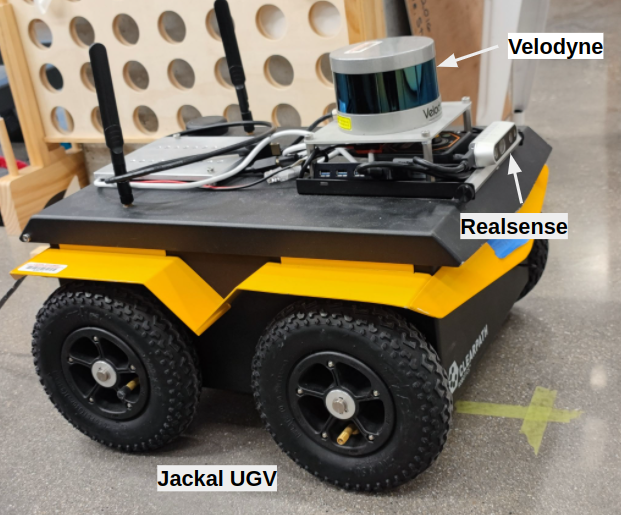
3D Simultaneous localization and mapping (SLAM) is a broadly used technology in mobile robots to map the environment and localize the robot. RTAB-Map is one of the most popular packages for 3D SLAM. The package can construct a 3D map with real-time performance and optimize the model based on close loop detections. This project, RTAB-map uses both sensor data from a Velodyne LiDar and a Realsense RGB-D camera as input in this project. A Jackal UGV was used as the mobile platform.
Another task in this project is to align color pixels from a camera to the point cloud sensed by LiDar. Colorized point clouds can provide a more realistic visualization and add another type of information to point cloud analysis. To colorize the point cloud by referencing images, an approach to obtain the extrinsic parameters transformed from one sensor device to another is essential. Thus, a calibration package was developed to compute the extrinsic parameters for devices sensing point cloud messages.
Video demo
Hardware
- Jackal UGV mobile platform
- Intel RealSense camera D435i
- Velodyne Puck LiDar sensor (VLP-16)
- PS4 Controller
The LiDar and camera are positioned on the top front of the Jackal UGV, as shown in the following picture.
Software
The project pipeline includes three stages.
Stage 1 - 3D SLAM Implementation:
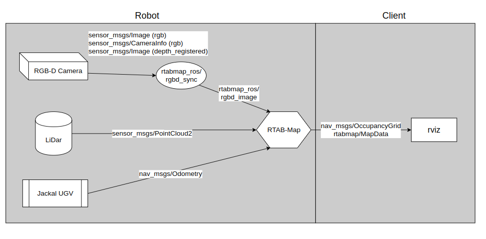
The Jackal robot is equipped with a LiDar and an RGB-D camera. The Lidar provides 3D point cloud messages to the mapping algorithm, while the camera provides both RGB images and depth-registered images. The flow chart below shows our configuration’s important messages used in rtabmap.
Rtab-map uses loop closure detection to optimize the map. The loop closure detector uses a bag-of-words approach to determine how likely a new image comes from a previous location or a new location. The easiest way to accomplish a loop closure is to control the robot rotating by itself. As shown in the following gif, when the robot spins around, both the point cloud map and grid map grow and become more certain about the environment.
The navigation stack is accomplished by the move base ROS package, which links together a global and local planner and publishes a twist control message to move the robot to the desired goal position. The move base works better when the robot has a more certain grid map. The following gif shows that the robot is implementing a navigation stack. Also, the move base package has many configuration parameters; good navigation requires a lot of tunning of those various parameters.
Stage 2 - Calibration Package:
A calibration ROS package is developed to find the extrinsic parameters between the Velodyne LiDar and Realsense camera. The point cloud colorization algorithm is accomplished by the transformation from point cloud 3D coordinates to image pixel coordinates. Thus, an accurate extrinsic parameter is crucial for good alignment between point clouds and images. Since the Realsense camera provides point cloud messages created by an active infrared stereo, the calibration task becomes easier as we only need to align two clusters of point clouds from two sensors. The package can also calibrate the extrinsic between two sensors that receive point clouds, such as two LiDars. The target object required for this project can be any rectangular prism or rectangular board. The calibration algorithm requires three corner coordinates from one face of the target object. Two ROS services are used to find and store the reference points. The following image shows an example to find one reference point from LiDar point cloud data.
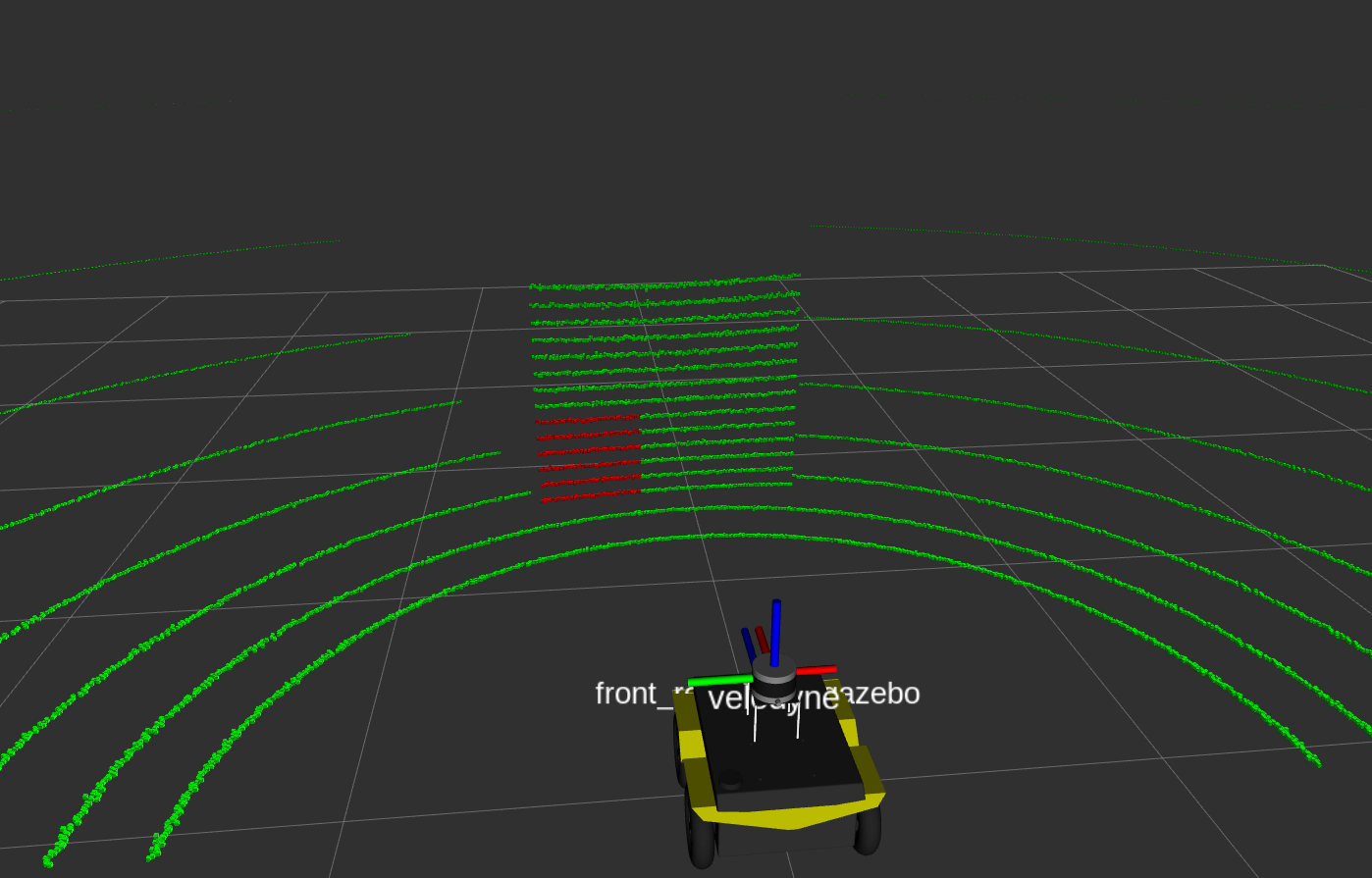
The green cloud indicates the timestamped lidar data, and the red square region is given by a ROS service with specific coordinates and the length of the square. Another ROS service is used to find the corner coordinates of the target region. More detailed instruction can be found in the README file of the calibration package repository.
Stage 3 - Colourisation algorithm:
The colorization algorithm is designed based on rigid body transforms and direct linear transforms (DLT). After performing the calibration package, we can obtain the transformation from LiDar to the camera. The point clouds collected by Lidar are initially in the LiDar frame (“/velodyne”). Using rigid body transforms, the LiDar point clouds can be converted to the camera frame (“/camera_depth_optical_frame”).
The direct linear transform (DLT) is a technique to jointly localize and calibrate a camera. Typically, the camera model has 11 degrees of freedom to calibrate six extrinsic and five intrinsic parameters. Since each Realsense camera comes with pre-calibrated intrinsic parameters, and those can be accessed by “/camera_info” topic, we can focus on computing the extrinsic parameters. The equation of DLT can be expressed as follow.
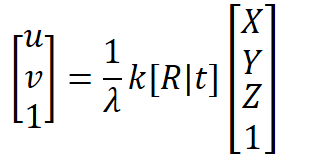
The left side of the equation is the homogenous representation of pixel coordinates in the camera plane, while the right side consists of λ (the value of Z after 3D coordinates have been transformed), k (the intrinsic matrix), R (the rotation matrix), t(the translation matrix), and the homogenous representation of point cloud coordinates in the camera frame.
After the point cloud coordinates have been mapped to the pixel coordinates in the camera plane, a threshold is set to obtain only the point that the camera’s field of view can receive. The RGB values are then added to those point clouds and published as XYZRGB point clouds in the camera frame.
Results and Analysis
Calibration:
The calibration package was tested in a simulation environment in Gazebo, where the extrinsic parameters are specified in the URDF files of our model. The ground truth transformation from the LiDar to the camera in [XYZ(meters)RPY(radians)] is [0.195,0.000,-0.128,-1.571,0.000,-1.571], while the calibrated extrinsic parameters gives a transform of [0.219, 0.023, -0.114, -1.566, 0.000, -1.581]. The errors are calculated to be [0.024,0.023,0.014,0.005,0.000,-0.01].
The translation errors are significantly larger than the rotation error. This error is because the timestamped lidar point cloud can not provide high-resolution point cloud data, especially the gap between each laser scan. As a result, the capture reference point may not be the corner of the plane of our target object. Moreover, the Gazebo simulation has little noise applied to those sensor data, while in reality, both sensors have higher noises. Typically the depth messages obtained by the Realsense camera have more considerable noises than the Velodyne LiDar.
Colourisation:
The colorisation algorithm can be run and displayed in real time. The following gif shows the demostration of the colorised clouds with real time performance.
The following two pictures show more detailed results each frame with a cheese board and a trash bin.
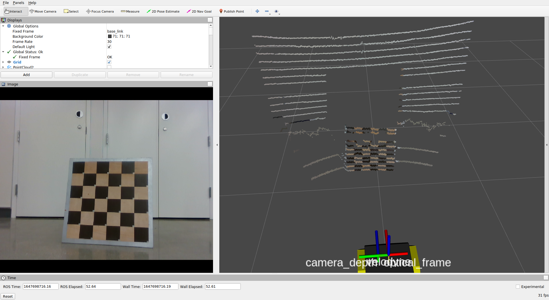
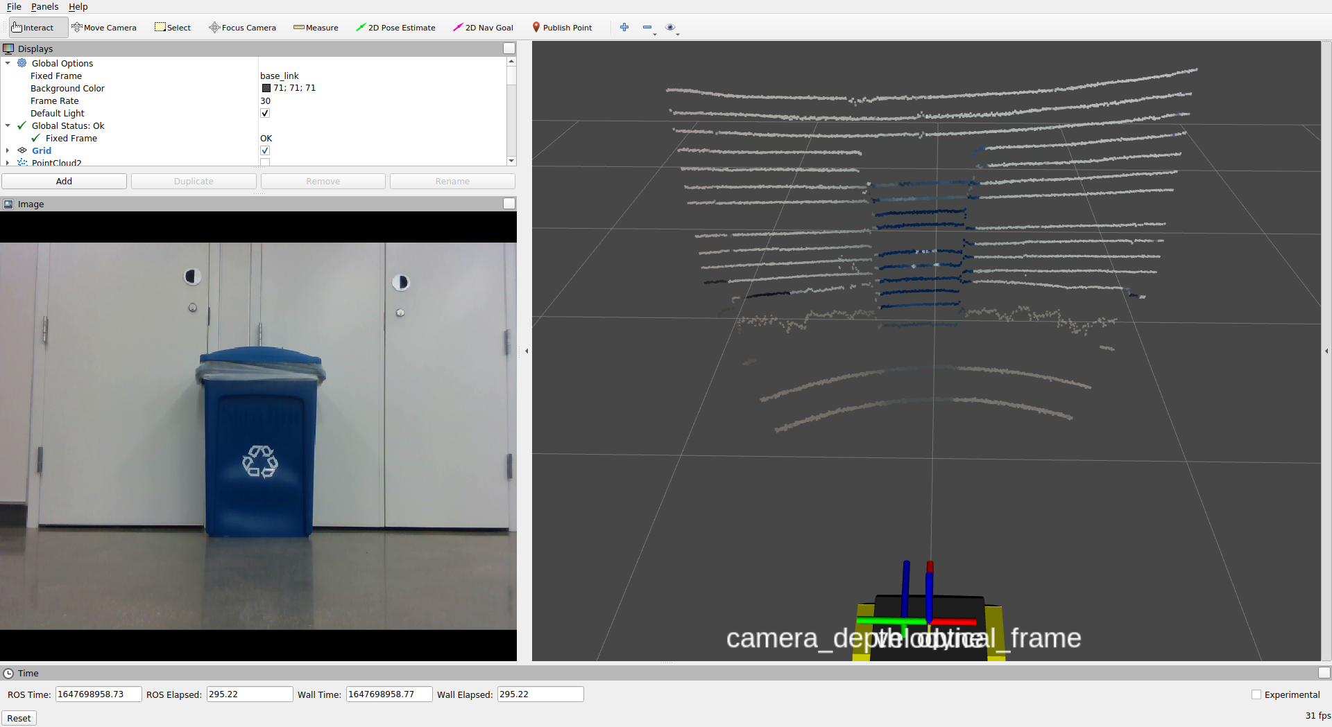
Due to the low resolution of the timestamped lidar point clouds, not enough RGB pixels were added to the point cloud. The accurate alignment of the color image and the point cloud depends on the performance extrinsic calibrations.
Future Scope
The current calibration packages only require a minimal amount of point data to perform the direct linear transform. An algorithm with more data points can be developed to optimize the accuracy of the data captured. The object’s corner is difficult to find due to the low resolution of point cloud data. To improve this, the calibration algorithm can be implemented directly to the 3D map cloud rendered by rtabmap, which has a higher resolution, but more points need to be processed. The same approach can be applied to the colorization algorithm to achieve higher resolution colorized clouds. Another way to obtain accurate point coordinates is to change the target object. The object could be changed to a plane with four circular-cut holes. By collecting the clusters around the circumference of the circle, we can apply circle detection algorithms to find its center. The circle fitting algorithm by A. Al-Sharadqah and N. Chernov is one of the most robust solutions.